>> SENDING SIGNALS BETWEEN INDEPENDENT CIRCUITS WITH OPTOCOUPLERS
After a long, cold and uneventful weekend; it was time to get back into playing
with electronics.
The most common use of an
optocoupler
(aka optoisolator, photocoupler) is to drive another circuit from an independent
one - much like I
previously covered; but what would be the best way to
connect an optocoupler for the sole purpose of sending signals from one
circuit to the other? I decided to do some research and see what I could
get working.
Of course; there are a couple of things to take into consideration -
especially when dealing with voltage levels that may vary. Considering the
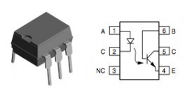
design of the optocoupler; it utilizes an LED to trigger a circuit
closure on the isolated circuit. When the input is hooked up to an
Arduino, we know the input is 5V - so, we can place an appropriate resister
to ensure the LED doesn't burn out.
So; what about higher voltages? I found a
online calculator
to determine the right resistor values.
The specifications of the optocoupler I am using states the diode maximum
forward voltage of 1.7V and has a current drawn of around 10mA. Depending
on the input voltage (5V, 9V, 12V, 24V) - the appropriate resistors would
need to be 330Ω, 820Ω, 1.2kΩ and 2.7kΩ respectively. Failure
to put the right resistor could burn out the LED quite quickly.
Now it time to figure out how to detect if the circuit is open or
closed - I came up with the following:
                     +---------------------------------- D0
                     |
     GND --[ 4.7k ]--+-----[        ]
     5V  ------------------[ (4n35) ]------------------- GND
                           [      . ]----[ 1.0k ]-+
                                                  |
                                                  +--/-- 5V
Basically; if there is no closed circuit; the signal being sent to D0
will be 0V (GND); tripping the optocoupler would then close the
circuit and push 5V on the same line. This would represent LOW
and HIGH respectively using the digitalRead()
function.
Hooking up and disconnecting power to PIN 1 (identified by a dot)
of the optocoupler in fact toggles the value on the the digital pin.
This is almost identical to how a push button functions; the 4.7kΩ
pull-up resister exists to avoid external electromagnetic noise from
it being a floating pin.
#define PIN_OC D0

void setup()
{
    pinMode(PIN_OC);
}

void loop()
{
    int val = digitalRead(PIN_OC);
    delay(50);
}
Now it is time to solve the next piece of the puzzle in the project I am
working on.
![[Valid RSS]](valid-rss-rogers.png "Validate my RSS feed")