>> ISOLATING INDEPENDENT CIRCUITS WITH OPTOCOUPLERS
Yet another handy electrical component everyone should be aware of - so many
uses!
An
optocoupler
(aka optoisolator, photocoupler) is quite an cool electrical component - it
allows to independent circuits that may be operating on different voltages
to allow one circuit to act as a switch within the other. The hardware
utilizes an LED on the initiating circuit to light up and allow a photosensor
on the receiver to trigger and close the circuit when triggered. Why does
this component exist and how can it be used in an IoT project?
There are two reasons to use an optocoupler:
- to isolate one circuit from another, each having different voltage
- prevent electrical noise or other voltage transients from interfering between circuits
In the majority of IoT projects; the first reason will most likely be
the reason for the decision to use an optocoupler. You may need to integrate
with an existing hardware solution that is simply not capable of using the
same voltage of your micro-controller. Remainding independent also means
you are in no way interfering with the various electrical certifications
the hardware may have.
It doesn't take much to setup a test environment to see an optocoupler
in action.
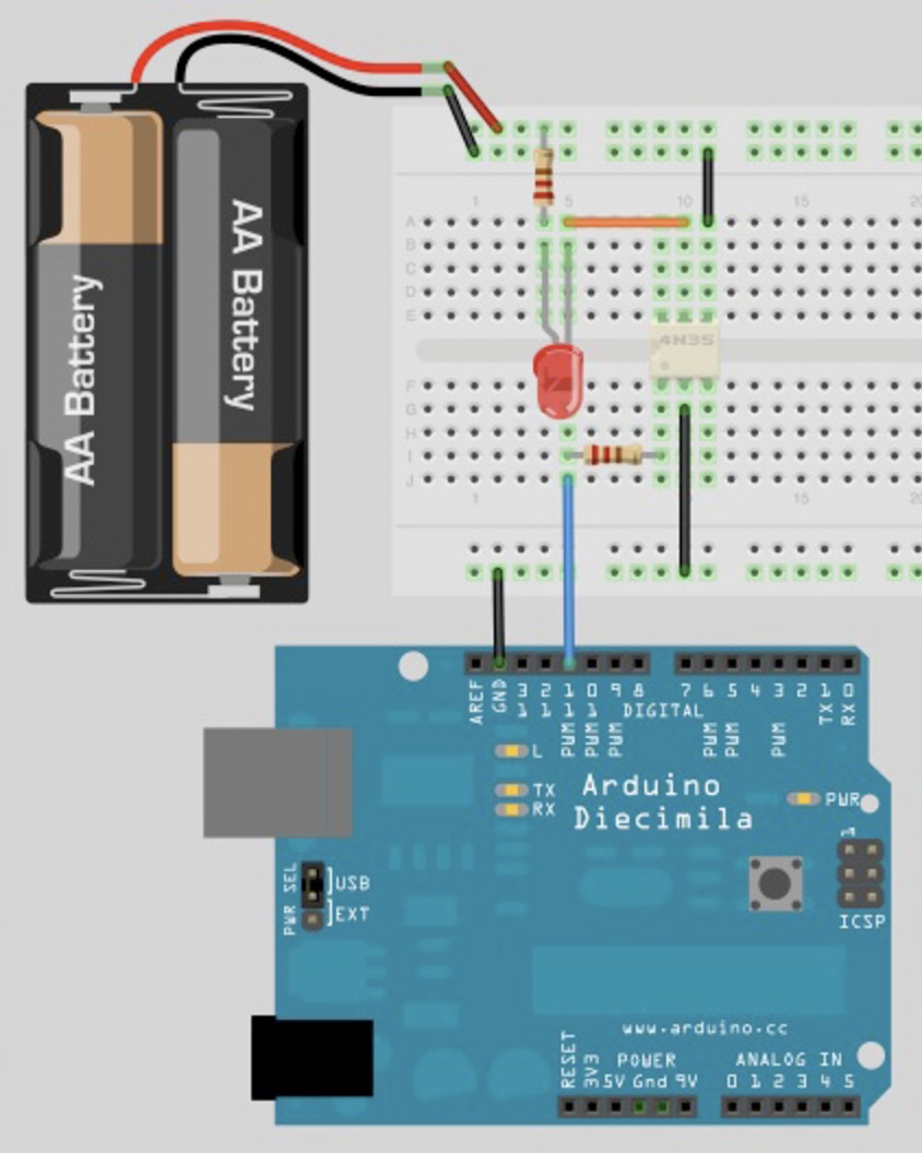
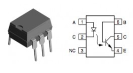
The key thing is to isolate pin 1 (normally denoted with a dot) and then
wire your signal source on the controller circuit to it; and pin 2 to the
associated ground signal. On the receiving circuit; isolate where you can
break the circuit in two - connect one end to pin 5 and the other to pin 6.
Keeping in mind the optocoupler has an LED - it doesn't hurt to throw a
resistor on the circuit so it doesn't fry when set HIGH.
When the optocoupler is set HIGH - it will effectively close the
circuit on the receiving side; setting it LOW will open it again.
A very simple sketch can make the LED blink and you can verify that the
optocoupler is functioning correctly - a sample sketch is provided below:
#define PIN_OC 11

void setup()
{
    pinMode(PIN_OC, OUTPUT);
}

void loop()
{
    digitalWrite(PIN_OC, HIGH);
    delay(500);
    digitalWrite(PIN_OC, LOW);
    delay(500);
}
To give you a real-world example; I am working on a project that has a
"blackbox" that operates at 12V and has four digital out signals on it
that get triggered when certain conditions are met. Unfortunately; the
specifications
for the Photon state that the operating voltage should be between
3.6 and 5.5 volts - sharing the power circuit would fry the Photon as soon
as it powers up!
I had a faulty component (was going crazy); the sketch and wiring is a
great test harness!
![[Valid RSS]](valid-rss-rogers.png "Validate my RSS feed")