>> BUILDING YOUR OWN REGULATED 5V CIRCUIT FOR IoT PROJECTS
I have an upcoming project that requires dual voltage powering; so it
was time to figure this out.
It is very common that your IoT project will utilize a single power source;
but there are some cases where you need to mix multiple voltage inputs -
without bringing in multiple power supplies. A simple solution is the
use of a voltage regulator, an electrical component that can take a variable
voltage input and regulate it to a specific output voltage. So; how does
such a setup look like?
A quick google search will find a number of instructables showing how
to do this; but after do so, I had a number of questions that most of
the videos, blog posts or hack descriptions didn't seem to answer all in
the same place - so, for my own understanding I did the research for you here.
The most important component is the voltage regulator itself; such as the
IC 7805 (5V regulator).
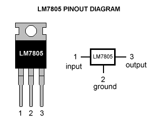
The IC 7805 accepts a variable input voltage, anything from 7V through to
35V (depending on the component being used) - always check the data sheets!
It will then output 5V. However, depending on the power source - it may
require additional components to stabilize the signal.
A lot of pages just say you need to use capacitors to do this; but not a
lot of them explain why. So, I started digging - what do capacitors actually
do within a circuit? Seems there are a lot of
technical descriptions
about them, but the basic version is that they are like batteries, that
store electrical signals that can discharge extremely fast.
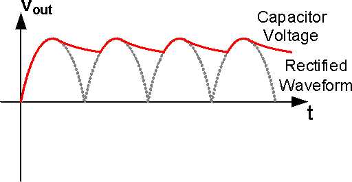
I found a nice
YouTube
video showing the effect of the signal output on such a circuit with and
without a capacitor. The fast charging and discharging of the capacitor allows
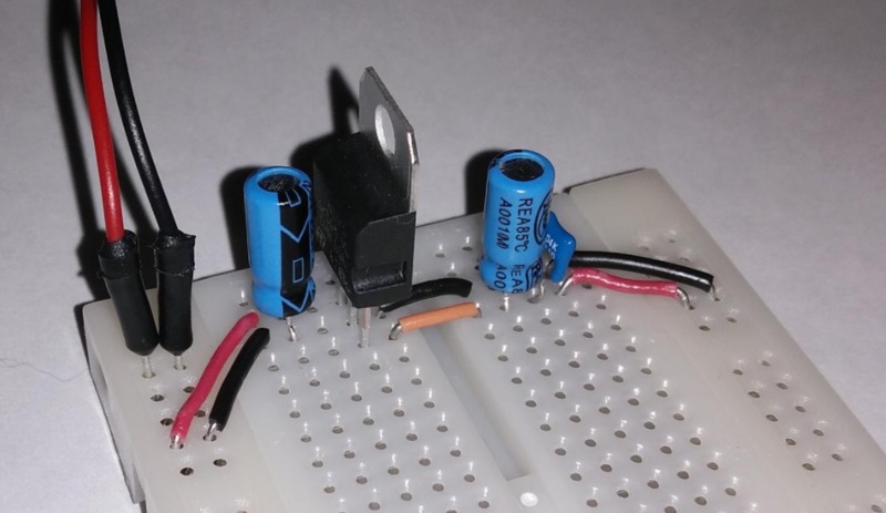
the signal to remain relatively flat (red line above). In my case; I used
a 22µF electrolytic capacitor on both the input and output voltages -
in addition a 0.1µF ceramic capacitor to de-couple the circuit from
the power supply. Just make sure you connect the polarized capacitors
correctly or *POOF* - always check.
With 12V DC power input, I connect my multimeter and see a nice 5.08V without
any load applied.
![[Valid RSS]](valid-rss-rogers.png "Validate my RSS feed")